From Engineering Drawings to Fabricated Structural Steel

Every steel structure starts with a design. But before a beam can be cut or a column can be welded, someone needs to translate that design into instructions the fabrication workshop can follow.
Structural steel fabrication drawings provide that essential link. They explain how individual steel components should be manufactured, helping turn engineering information into finished pieces ready for construction.
If you are ordering steel for a warehouse, home extension, workshop or commercial project, understanding this journey can make the process much easier. You will know what information your supplier needs, why drawing reviews matter and what happens before your steel arrives on site.
Let’s follow the process from the first engineering drawings to the finished steelwork.
What Are Structural Steel Fabrication Drawings?
Structural steel fabrication drawings are detailed documents used to manufacture the steel components required for a project. Often called shop drawings, they communicate the dimensions, materials and fabrication details needed to produce individual parts and assemblies.
An engineering drawing might identify a beam’s size and position in the building. The fabrication drawing explains how that particular beam needs to be made, including its finished length, holes, cuts and attached plates.
There can also be different drawing types within the same package. A single-part drawing describes an individual component, such as a plate. An assembly drawing shows how several components fit together to create a fabricated item. Tekla’s documentation describes assembly drawings as workshop drawings that typically show a main part and secondary parts connected to it.
For the workshop, these drawings provide a shared reference. Instead of interpreting the overall building design independently, the fabrication team works from coordinated instructions for each item.
Read more: How Structural Steel Shop Drawings Work
How Engineering Drawings Establish the Starting Point
Engineering drawings describe the structure’s design requirements. They show the arrangement of beams, columns, bracing and other structural elements, alongside relevant sizes, levels and specifications.
However, they are not always intended to describe every workshop operation. A design may identify a connection arrangement without showing every individual plate as a separately dimensioned manufacturing component.
This is where steel detailing begins. The detailer develops the fabrication information from the engineering documents while coordinating it with the wider project.
Architectural drawings may influence where steel can sit within walls or ceilings. Building services may require clear space around a beam. Existing construction may introduce dimensions that need to be measured on site.
The quality of this starting information matters. If a supporting wall’s location is uncertain, producing a precise beam drawing does not remove that uncertainty. The underlying dimension still needs confirmation.
How Structural Steel Fabrication Drawings Are Prepared
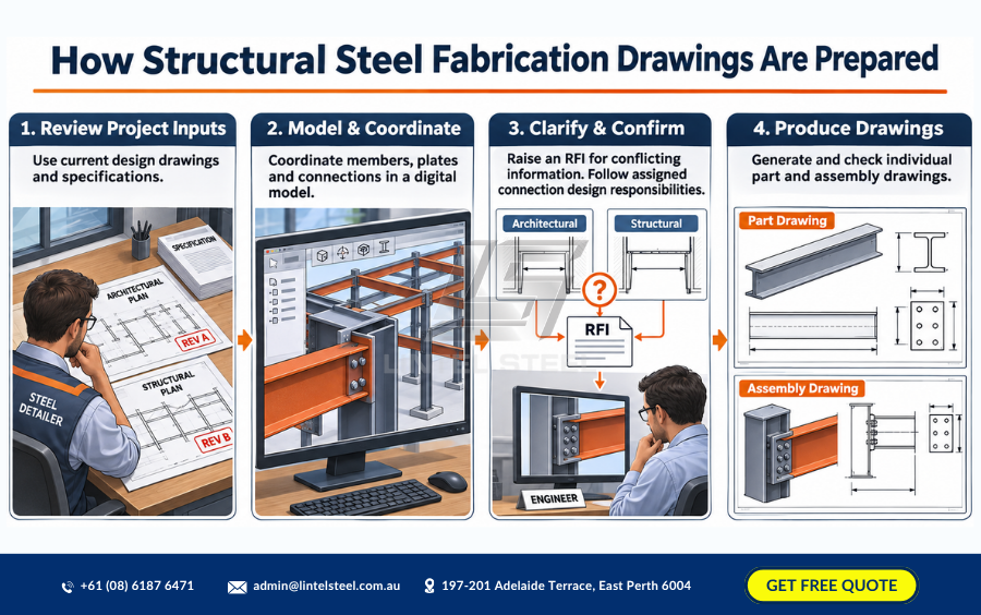
A steel detailer usually prepares the fabrication drawings using the project’s current design documents and specifications. Depending on the project, the detailer may work within the fabrication company or as an independent specialist.
Many teams develop a digital model of the steelwork before producing drawings. This helps them coordinate the geometry of members, plates and connections. Drawing software can produce individual part and assembly drawings from that information.
However, software does not automatically resolve missing design decisions. Someone still needs to check the inputs, interpret the project requirements and raise questions when information conflicts.
For example, an architectural drawing might show a wider opening than the structural drawing. The detailer should seek clarification through the agreed project process, often using a request for information, or RFI.
The connection design arrangement also needs to be clear. Some projects provide complete connection designs, while others assign specified connection design work to a specialist engineer. The detailer should follow the established responsibilities rather than make unapproved structural decisions.
What Structural Steel Fabrication Drawings Show
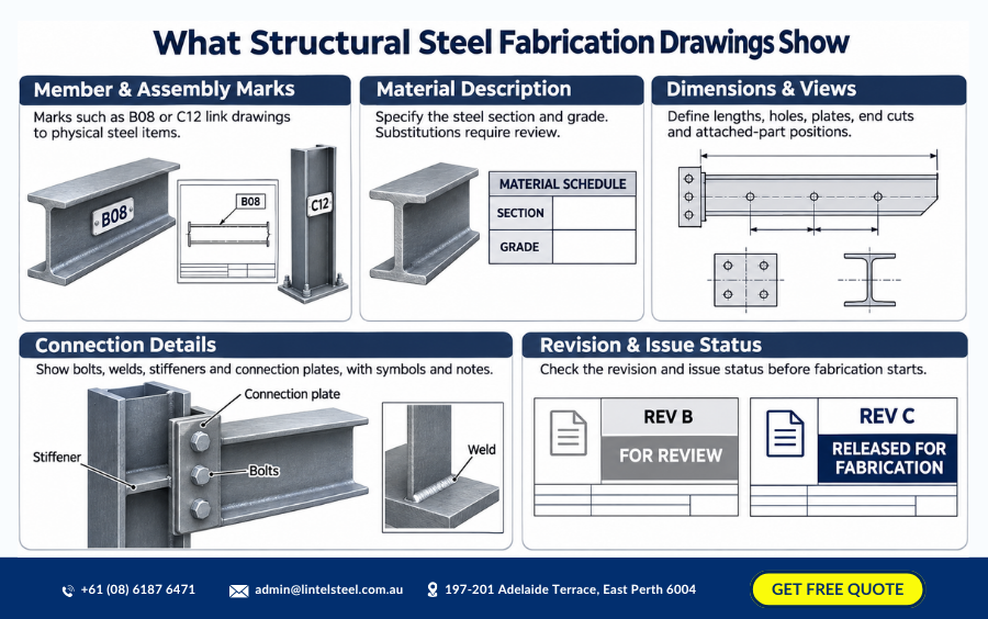
A fabrication drawing brings together the information needed to identify and manufacture a component.
The member or assembly mark is an important starting point. A reference such as B08 or C12 connects the drawing to the physical steel item and related project documentation.
The material description identifies the required steel section and grade. This distinction matters because two sections that look similar may have different properties. Availability alone is not a reason to substitute one for another.
Dimensions explain the component’s geometry. These may include its overall length, hole locations, plate sizes, end cuts and the positions of attached parts. Different views and sections help show details that would be unclear in a single view.
Connection details communicate how the parts join together. Bolts, welds, stiffeners and connection plates may all appear, with symbols and notes describing the requirements.
The drawing should also make its revision and issue status clear. A drawing issued for review is at a different stage from one released for fabrication. Understanding that distinction helps prevent work from starting on information that is still being checked.
Reviewing and Releasing the Drawings
Before fabrication begins, the drawing package needs to move through the checking and review process established for the project.
The fabricator’s checking focuses on matters such as dimensions, quantities, member identification and how the parts fit together. Other reviewers examine the information within their assigned responsibilities.
This distinction is important. Reviewing a drawing does not mean every responsibility transfers to the person reviewing it. As one industry example, the AISC Code of Standard Practice identifies the fabricator’s responsibility for checking and coordinating dimensions, details, member sizes, fit-up and material quantities when preparing approval documents. The contract and applicable local requirements determine the arrangements for a particular project.
Comments may lead to revisions and another submission. Once the necessary requirements have been addressed, the appropriate drawings can be released for production.
For customers, this stage is a useful opportunity to confirm practical matters, including agreed openings, visible steelwork and dimensions connecting to existing construction. Structural design questions should remain with the responsible engineer.
Selecting and Preparing the Steel
Once the required information is released and materials are available, production can move forward.
The workshop identifies the steel sections and plates needed for the job. Depending on the project requirements, supporting material documentation may also need to be checked and retained.
The components are then prepared for fabrication. A beam might require cutting to length, while a plate may need profiling and holes. Other pieces may need end preparation so they can connect correctly.
It is helpful to understand that fabrication is a sequence of coordinated activities. Cutting, hole making, fitting, welding, cleaning and coating can all form part of the process, followed by inspection and shipping. The exact route depends on the component and the project specification.
A simple stock-length order therefore involves a different scope from an order for finished assemblies. That difference should be reflected clearly in the quotation and delivery programme.
From Cut Parts to Finished Assemblies
After the individual parts are prepared, the workshop brings them together according to the fabrication information.
Consider a column with a base plate and several connection plates. Each piece must be positioned correctly relative to the others. The base plate’s orientation matters, as do the positions of the plates that will connect to beams.
This is why a fabrication drawing needs more than an overall length. A column can have the correct height but still create problems if a connection plate faces the wrong direction.
The workshop follows the specified assembly and welding requirements, with checks at relevant stages. Finding an issue while parts are being fitted can make correction easier than discovering it after the assembly is complete.
Fabrication methods also need to account for accuracy and the effects of the work itself. Welding, for example, introduces heat, so the production team must manage the process to achieve the required finished geometry.
Inspection, Surface Treatment and Delivery
The journey does not end when the last weld is complete.
Inspection and testing depend on the project specification, applicable requirements and the fabricator’s quality procedures. These activities may address dimensions, welds, materials and other relevant characteristics.
Surface treatment is another part of the order that should be agreed early. The specified system may involve painting, galvanizing or another treatment suitable for the project. Preparation and application requirements affect both production and scheduling.
Quality management should cover the broader fabrication process rather than rely entirely on a final visual check. AISC’s information for certified fabricators, for example, describes a quality management system extending from quality goals and employee training through to product delivery.
Before dispatch, components need clear identification so the site team can match them to the relevant erection information. Delivery planning should also consider site access, unloading arrangements and the order in which the steel is needed.
A Practical Example: Fabricating a Warehouse Beam
Imagine a warehouse project that requires a roof beam connected to columns at both ends.
The engineering drawings establish the specified beam and structural arrangement. The detailing process then develops the information needed to manufacture that individual assembly.
Its fabrication drawing identifies the beam mark, finished length, end details and any attached connection components. These details are coordinated and reviewed before release.
Now suppose the spacing between the supporting columns changes during design coordination. That adjustment could affect the beam length and related connection information.
If the change is resolved before fabrication, the drawings can be updated and the workshop can work from the revised information. If cutting has already started, the project team must assess what the change means for the material, completed work and schedule.
This example shows why drawing coordination is part of production planning. It helps establish what should be manufactured before the workshop commits resources.
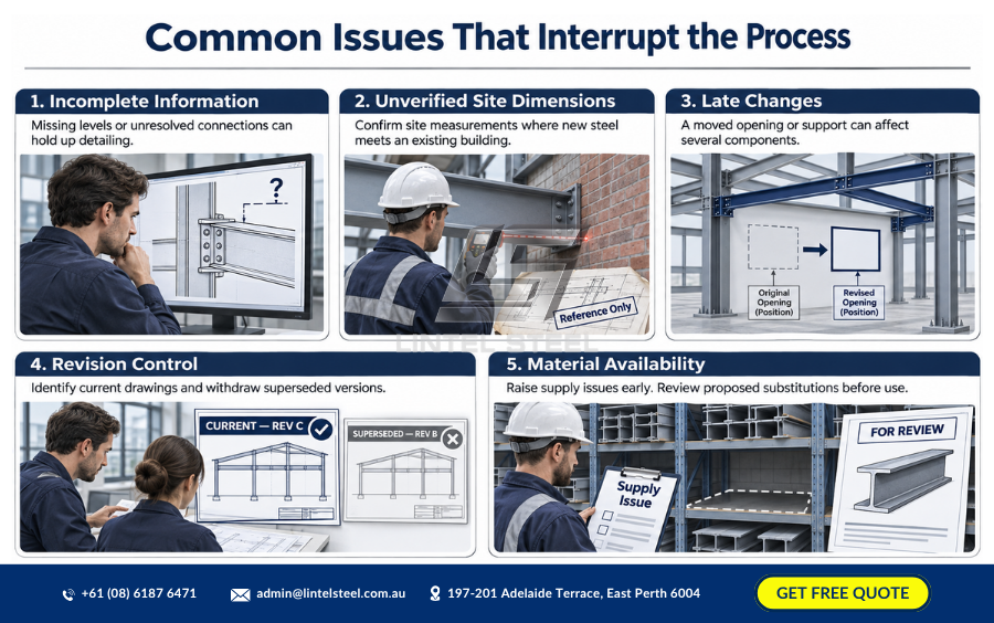
Common Issues That Interrupt the Process
Incomplete information is a frequent source of difficulty. A missing level or unresolved connection may prevent the detailer from completing an otherwise straightforward component.
Unverified site dimensions can also create uncertainty, particularly where new steel meets an existing building. Old drawings are useful references, but they may not reflect every site condition.
Late changes introduce another challenge. Moving an opening or adjusting a support can affect several components, even when the visible change appears small.
Revision control is equally important. The project needs a reliable way to identify current drawings and withdraw superseded versions. Otherwise, two teams could unknowingly be working from different instructions.
Material availability can require discussion too. If the specified product cannot meet the programme, the supplier should raise the issue early. Any proposed substitution needs to follow the appropriate review process.
What to Provide When Requesting Fabricated Steel
A useful enquiry gives the supplier a clear picture of both the product and the required service.
Provide the current engineering drawings, relevant specifications, quantities and intended delivery location. Explain whether you need stock steel, processed components or complete fabricated assemblies.
If structural steel fabrication drawings already exist, share their current revision and status. If they still need to be prepared, clarify who will arrange detailing and the required reviews.
Finishes, delivery dates and site restrictions also affect the scope. A supplier needs to know whether steel must arrive in stages, whether unloading space is limited and whether particular components are required first.
Before accepting a quotation, check what it includes. Material supply, detailing, engineering, fabrication, surface treatment, transport and installation can involve separate responsibilities and costs.
Turning Clear Drawings into Steel Ready for Construction
The route from engineering drawings to fabricated structural steel depends on accurate information, coordinated detailing and controlled production.
Structural steel fabrication drawings make that connection practical. They translate the design into identifiable parts and assemblies, giving the workshop the information needed to prepare the steel.
If you are planning a steel purchase, start by gathering your current drawings and discussing the required scope with your supplier. Clear information about materials, fabrication, finishes and delivery gives your project a stronger foundation before production begins.